View methods side by side.
Choose up to four methods. Add them using the search and share the comparison by copying its link.
| Criterion | 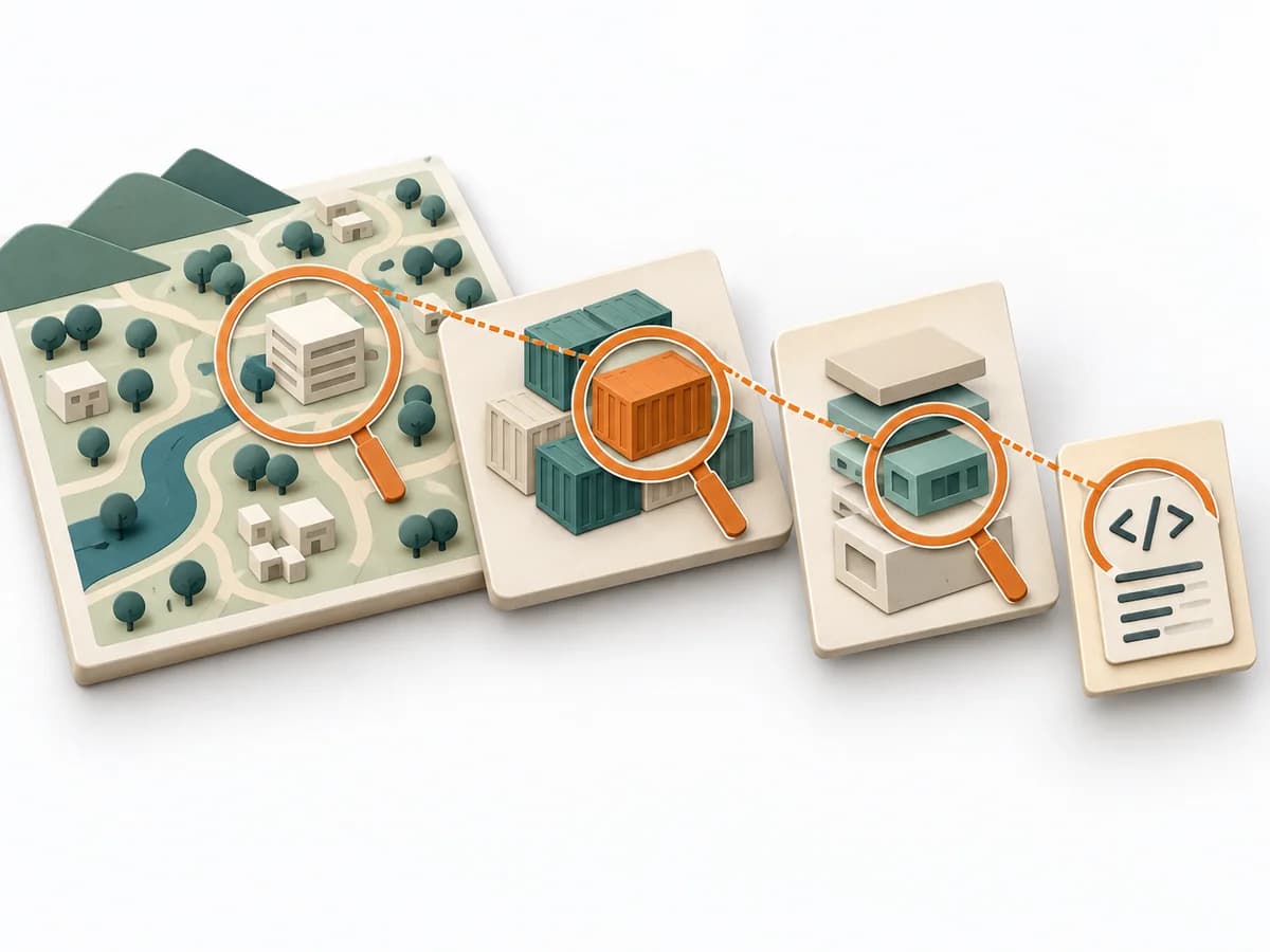 Architecture C4 Model | 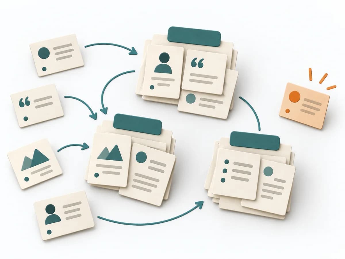 UX Research Affinity Diagramming | 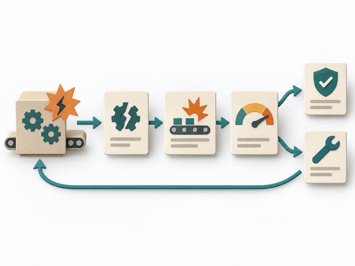 Operations Failure Mode and Effects Analysis | 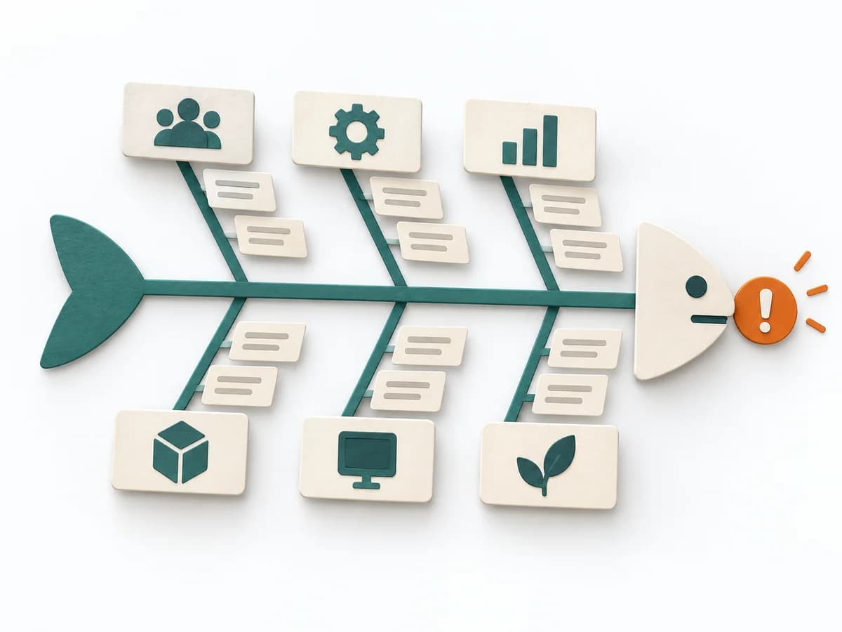 Operations Fishbone Diagram |
|---|---|---|---|---|
Purposedifferent | The C4 Model makes a system legible across several resolution levels, from context down to code. It suits situations where different audiences need to understand the same architecture from different altitudes. | When research notes, feedback, or observations sit unconnected side by side, affinity diagramming sorts the raw material into solid themes. Many individual points turn into patterns that make decisions and opportunities clearer. | For a process, product, or service with noticeable failure risks, the method assesses possible failure modes in advance. It directs attention to combinations of occurrence, effect, and detectability. | When a problem has several possible contributing factors, the method sorts causes by cause areas. It prevents an initial hunch from blocking the view of other plausible drivers. |
Complexitydifferent | Low | Low | High | Low |
Timedifferent | 1-4 h | 45–90 min | 2-6 h | 30-60 min |
Participantsdifferent | 1-5 | 3-10 | 3-10 | 2-8 |
Formatdifferent | Workshop + async | Workshop | Workshop | Workshop |
Outputdifferent | Context Diagram, Container Diagram, Component Diagram | Theme clusters, Insight statements, Opportunity areas | FMEA Table, Risk Priority, Mitigation Actions | Fishbone Diagram, Cause Categories, Investigation Backlog |
Tagsno overlap | ArchitectureCommunicationVisualization | SynthesisQualitativeRoot cause | RiskQualityOperationsRoot cause | Root causeQualityOperations |